T-SIM V4.5 Reference
Example 2: Plug assisted negative forming
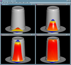
Click here to see video (74 kB).
| Back to Tutorial | Previous Example | Next Example |
Creating representation of tools
In this example there are two tools. The mold does not move and it is represented by Tool 1. The plug is movable and it is represented by Tool 2. Both tools are quite simple (axisymmetrical) and they can be created directly in T-SIM.
Creating the mold
The mold used in this example is quite simple and it can be created directly in T-SIM. Just click on New Tool on T-SIM shortcuts bar, select Create new tool ('ABR" editable representation) and click OK. Create new tool representation dialog appears. Please fill in the dialog as follows: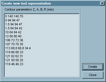
Each line in the dialog specifies z level of a contour, its dimensions and radius in corners. Contours are created along z axis, i.e. center of any contour is [0, 0, z]. This must be taken into account when creating a sheet - the center must have coordinates [0, 0, 0]. Moreover, the final contour is automatically closed by T-SIM, so it is not necessary to specify a final contour like "0 0 0 0" to close the tool.
Used data (use Copy & Paste to copy the data to T-SIM dialog):
0 140 140 70
0 94 94 47
1.5 94 94 47
1.5 84 84 42
10 84 84 42
12 80 80 40
106 72 72 36
107 70 70 35
113 68.8 68.8 34.4
119 66 66 33
121 62 62 31
121 50 50 25
119 46 46 23
Click Create. The following window with the new tool created appears on the screen:
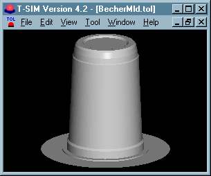
Click File / Save and save the tool - use "\Becher" folder, file name "BecherMld.tol".
For more information about creating tools please see Reference - Tools.
To create the plug, just click on New Tool on T-SIM shortcuts bar, select Create new tool ('ABR" editable representation) and click OK. Create new tool representation dialog appears. Please fill in the dialog as follows:
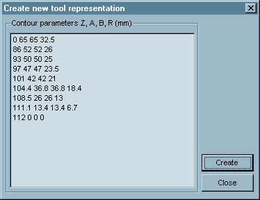
Each line in the dialog specifies z level of a contour, its dimensions and radius in corners. Contours are created along z axis, i.e. center of any contour is [0, 0, z]. This must be taken into account when creating a sheet - the center must have coordinates [0, 0, 0].
Used data:
0 65 65 32.5
86 52 52 26
93 50 50 25
97 47 47 23.5
101 42 42 21
104.4 36.8 36.8 18.4
108.5 26 26 13
111.1 13.4 13.4 6.7
112 0 0 0
Click Create. The following window with the new tool created appears on the screen:
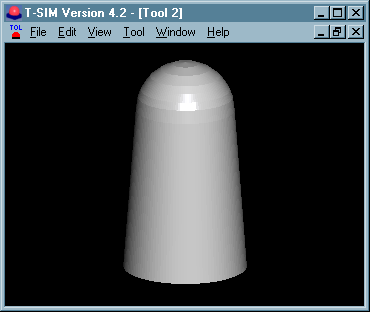
Click File / Save and save the tool - use "\Becher" folder, file name "BecherPlg.tol".
Now, because the plug starts its movement below a sheet, we have to shift it so its top has z coordinate equal to 0. Click Tool / Move and in Tool move dialog, specify the following values:
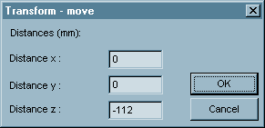
Click File / Save to save the shifted plug. To make sure its top has z = 0, click Tool / Properties. Dialog with tool properties appears - check the values and click OK to close the dialog.
Dimensions of any sheet should be equal or smaller than x and y dimensions of the tool. When the dimensions of a sheet are bigger the sheet can inflate during simulations without any restrictions and it can lead to instabilities. However, this problem can be solved also by adding clamping to the sheet - for more information please see Reference - Adding clamping to sheet.
Any sheet in T-SIM is always created in x-y plane with z coordinate equal to zero.
The simulated part is axisymmetrical So it is not necessary to solve deformation of the whole sheet. It is enough to use just one quarter of the sheet.
To create the sheet representation in T-SIM, just click New Sheet on T-SIM shortcuts bar. Create new grid (sheet) representation dialog appears. Please fill in the dialog as follows:
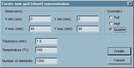
Do not forget to specify "Quarter" as a symmetry type.
Click Create. A window with the new sheet created appears on the screen. Click File / Save and save the grid (sheet) - use "\Becher" folder, file name "Becher.bcs".
Process control
In this case the tool 1 (mold) does not move. It is above the sheet so it behaves as upper.
The tool 2 (plug) is used to pre-stretch the sheet. It starts its movement below the sheet so it behaves as lower.
When the plug is in its final position, a pressure is applied to inflate the sheet.
To create a file to describe the tool 2 movement and the pressure applied, click New Process Control on T-SIM shortcuts bar. Fill in the table with the following time and pressure values:
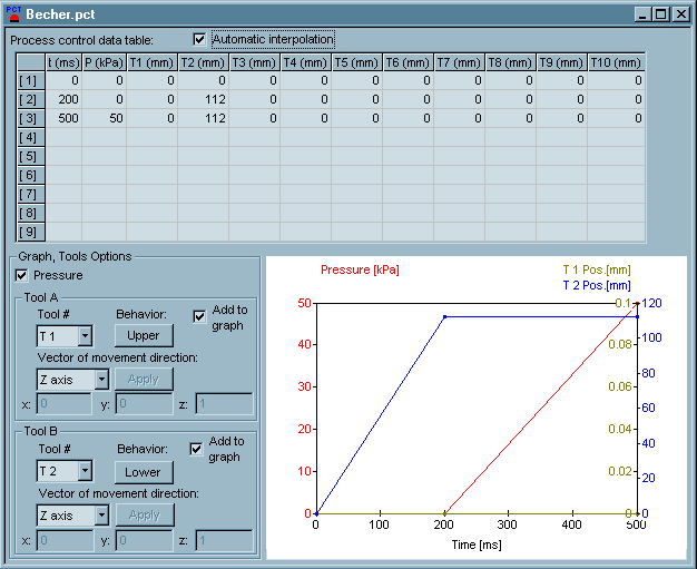
Tool 1 does not move and in its file, the tool is located in correct position. For this reason, the position of tool 1 are equal to 0 during whole process. Tool 1 behaves as upper, so the button under "Behavior" text has label "Upper" on it. (Click the button repeatedly to switch between Upper / Lower behavior").
Tool 2 moves from 0 ms to 200 ms: Its initial position is 0 mm (tool top touches the bottom side of the sheet). The final position at 200 ms is 112 mm (tool travels 112 mm in direction of z-axis from it initial position). The vector of movement has to be z-axis, Tool 2 behaves as lower.
The mold is evacuated from 200 ms to 500 ms using vacuum 50 kPa.
Click File / Save and specify a file name for process control data - use "\Becher" folder, file name "Becher.pct". Then click File / Close to close Process Control window.
For more information about tool behavior and process control setting see Reference - Process control.
Click New Heat & friction on T-SIM shortcuts bar. Fill in the dialog with the following values (first dialog for Tool 1, second for Tool 2). To switch between tools, use combo box "Tool #". To confirm changes in selected tool's data, click on Apply changes in tool data.
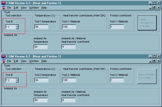
Click File / Save and specify a file name - use "\Becher" folder, file name "Exa.hfr".
For information about values of heat transfer coefficients and friction coefficients please see Reference - HFR.
Setting up the project
To set up a project click New Project on T-SIM shortcuts bar.
Use Browse buttons to select:
| Sheet | Becher.bcs |
| Tool 1 | BecherMld.tol |
| Tool 2 | BecherPlg.tol |
| Material | Pp.vie (in this example PP from T-SIM material database is used) |
| Process control | Becher.pct |
| Heat & friction | Exa.hfr |
Specify more details about this project in Additional information (optional).
Click File /Save to save the new project. Specify the project name (Becher.tff). When the project is saved, click Project / Solve to start the project simulation. Within short time the project is solved and you can view results in post processing - just click on Project / Open for post-processing. To learn more about post processing please see Reference - Post processing.
| Back to Tutorial | Previous Example | Next Example |