T-SIM V4.5 Reference
Example 3: Positive forming

| Back to Tutorial | Previous Example | Next Example |
Creating the tool representation
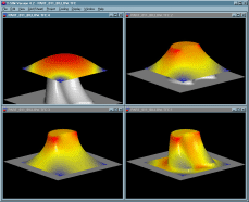
In this example there is just one tool - a movable mold. This mold is represented by T-SIM tool 2 (lower tool). It is quite complicated so there is no easy way how to create it. CAD software (SurfCam, SolidWorks, Catia, Pro-Engineeg etc.) must be used. Once the tool is created in CAD, its STL representation can be directly imported into T-SIM.
 |
 |
| Tool in CAD | STL representation |
STL files are not delivered with T-SIM. The following instructions are informative only. To solve this example, use directly Part_01.tol. This file is delivered with T-SIM (whole project is in the directory \Part01).
To import a tool represented in STL format into T-SIM just click New Tool, select Import new tool from STL and press OK. Then specify the imported file name (Part_01.stl) and click Open.
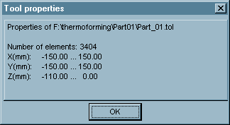
Once the tool is imported, click Tool / Properties to get information about the tool dimensions:

The dimensions of the tool base are :
X: -150 ... 150 mm
Y: -150 ... 150 mm
We will use this values when creating the sheet representation.
Important:
The tool maximal z coordinate is equal to
0 - this is because the tool will work as a plug - it will start its
movement below the sheet and will move in the direction of the positive
z axis.
Click File / Save to save the tool - use "\Part01" folder, file name "Part_01.tol".
Creating the sheet representation
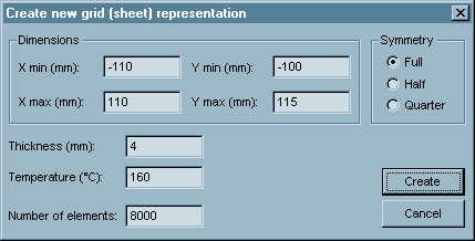
To create the sheet representation in T-SIM, just click New Sheet on T-SIM shortcuts bar. Create new grid (sheet) representation dialog appears. Please fill in the dialog as follows:

The sheet is smaller than the flange of the tool used. Do not forget to make sure that "Full" symmetry type is selected.
Click Create. A window with the new sheet created appears on the screen.
Click File / Save and save the grid (sheet) - use "\Part01" folder, file name "FEM.bcs".
For more information about creating sheets see Reference - sheet.
In this example pre-blowing is used. Before the mold starts to move, a bubble is created. Then the mold is moving up into the bubble. When it reaches its final position, a pressure from the opposite side of the sheet is applied to form the sheet into the final shape. So we have to describe the tool movement and pressure data.
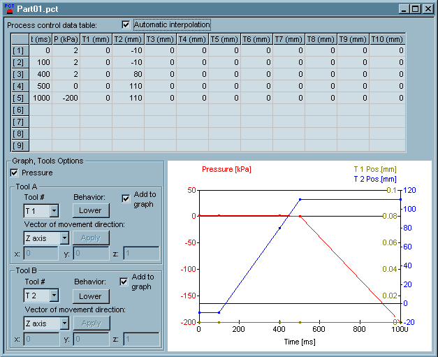
The tool movement: From 0 ms to 100 ms the mold does not move. During this time a bubble is created (see the pressure description below). From 100 ms to 500 ms the mold moves up from -10 mm to its final position 110 mm.
Pressure: From 0 ms to 400 ms, constant pressure 2kPa is applied to create the bubble. Then the pressure is decreased to 0 kPa. At 500 ms, pressure from opposite side of the sheet is applied. It is increasing from 0 kPa at 500 ms to 200 kPa at 1 s.
Click New Process Control on T-SIM shortcuts bar. Fill in the table with the following time and pressure values:

You do not have to specify positions of the tool 1 - in this example, the tool 1 is not used.
Tool 2 is used as a lower tool, so it behaves as lower. Direction of movement is z-axis.
Click File / Save and specify a file name for process control data (Part01.pct). After the saving click File / Close to close Process Control window.
For more information about tool behavior and process control setting see Reference - Process control.
Heat and friction data
Click New Heat & friction on T-SIM shortcuts bar.

Select "T 2" in Tool #, fill in the values. Values for Tool 1 can be left default, because Tool 1 is not used.
Click "Apply changes...", then File / Save and specify a file name - use "\Part01" folder, file name "Part_01.hfr".
For information about values of heat transfer coefficients and friction coefficients please see Reference - HFR.
Setting up a project
To set up a project click New Project on T-SIM shortcuts bar.
Use Browse buttons to select:
| Sheet | FEM.bcs |
| Tool 1 | Part_01.tol |
| Material | PvcHard.vie (in this example hard PVC from T-SIM material database is used - the directory \Material) |
| Process Control | Part_01.pct |
| Heat & friction | Part_01.hfr |
Specify more details about this project in Additional information (optional).
Click File / Save to save the new project. Specify the project name (Part_011_billow.tff). When the project is saved, click Project / Solve to start the project simulation. Within short time the project is solved and you can view results in post processing - just click on Project / Open for post-processing. To learn more about post processing please see Reference - Post processing.
| Back to Tutorial | Previous Example | Next Example |