T-SIM V4.5 Reference
Example 4: Thermoforming with both tools movable
| Back to Tutorial | Previous Example | Next Example |
Creating the representation of tools
In this example there are two tools - the mold and the plug. Both tools are quite complicated so they were created in CAD and imported via STL files.

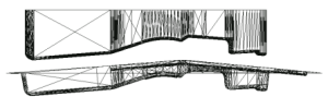
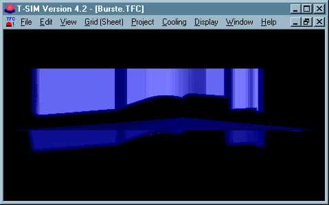
Tool file names are Obburste.tol (the tool 1 - behaves as upper) and Wkburste.tol (the tool 2 - behaves as lower). To learn more about importing the general tool representations into T-SIM please see Reference - Tool Import.
It is the user's responsibility to shift and rotate the tools so that they are in correct positions. T-SIM does not check for any collisions during the tool movements. A collision between the tools can lead to instabilities. It this case, the plug (the tool 1) must fit into the cavity of the mold (the tool 2).
STL files are not delivered with T-SIM. To solve this example, use directly *.tol files delivered with T-SIM (whole project is in the directory \Burste).
Creating the sheet representation
This part has no symmetry. We have to create the whole sheet.
To create the sheet representation in T-SIM, just click New Sheet on T-SIM shortcuts bar. Create new grid (sheet) representation dialog appears. Please fill in the dialog as follows:
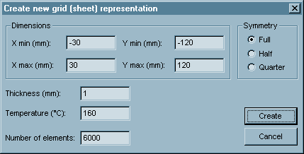
Click Create. A window with the new sheet created appears on the screen.
Click File / Save and save the grid (sheet) - Burste.bcs.
Process control
In this case both tools are movable.
Specify time, tools positions and pressure values as displayed in the following dialog.
Make sure that Tool 1 behavior is set to "Upper"
and it moves in z-axis direction.
Make sure that Tool 2 behavior is set to "Lower"
and it moves in z-axis direction.
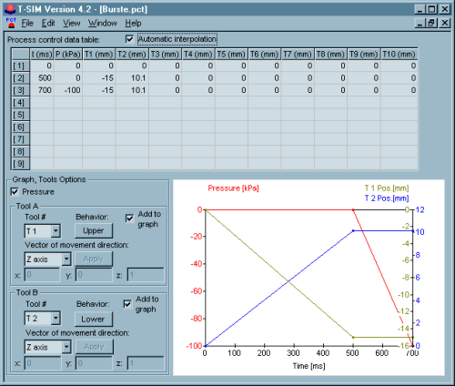
Click File / Save and specify a file name for process control data (Burste.pct). Then click File / Close to close Process Control window.
For more information about tool behavior and process control setting see Reference - Process control.
Heat and friction data
Click New Heat & friction on T-SIM shortcuts bar.
Fill in the dialog with the following values (first dialog for Tool 1, second for Tool 2). To switch between tools, use combo box "Tool #". To confirm changes in selected tool's data, click on Apply changes in tool data.
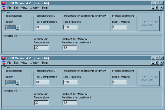
Click File / Save and specify a file name (Burste.hfr).
For information about values of heat transfer coefficients and friction coefficients please see Reference - HFR.
Setting up a project
To set up a project click New Project on T-SIM shortcuts bar.
Use Browse buttons to select:
| Sheet | Burste.bcs |
| Tool 1 | Obburste.tol |
| Tool 2 | Wkburste.tol |
| Material | Pp.vie (from the directory \Material) |
| Process Control | Burste.pct |
| Heat & friction | Burste.hfr |
Specify more details about this project in Additional information (optional).
Click File / Save to save the new project. Specify the project name (Burste.tff). When the project is saved, click Project / Solve to start the project simulation. Within short time the project is solved and you can view results in post processing - just click on Project / Open for post-processing. To learn more about post processing please see Reference - Post processing.
| Back to Tutorial | Previous Example | Next Example |