

B-SIM V2.5 Reference - Blow molding simulation

Process control
Process control document is used to store the description of the applied pressure / vacuum and movements of tools. Maximum of ten tools is supported. This means that for one simulation, ten tools are available with independent movements.
Creating new process control
Process control description
Pressure
Tool behavior and movement
Behavior
Movement
Extrusion control settings (AWT/PWT/SFDR)
(new in B-SIM Version 2.35)
Example
How to simulate various blow molding processes
Process control creation
To create a new process control, click on the icon with the tool tip "New process control" on B-SIM shortcut bar or click on File / New and select B-SIM Process control as the document type and click OK.
The following window appears:

Extrusion blow molding:
Starting from the version 2.35, parison extrusion can be simulated in
B-SIM. To include parison extrusion into a simulation, check Include
extrusion control at the top of the process control window. Details
about the extrusion control can be found in Extrusion
control settings.
Important:
The extrusion process itself, when included into simulation, delays
the molding process until the required parison length is reached. You
can specify the basic process control as starting at time 0, and B-SIM
will automatically add a time shift obtained due to the extrusion process.
Fill in the process control data table with appropriate data.
Specify the pressure and the tool(s) position at the time entered in the first column. Data in the process control table have to be specified using the following rules - see Process control description.
To add, remove or insert a new row into the table, press the right mouse button inside the table and select the required command from the pop-up menu displayed.
Check Automatic interpolation to force B-SIM to automatically interpolate missing pressure and position values.
In the Graph, Tools options, check Pressure to display pressure profile in the graph.
Tool A (and also Tool B) group enables to describe to select a tool and to describe its behavior, movement vector, and add the tool movement profile to the graph:
- First, select a tool to edit / include to the graph using the combo box "Tool #".
- Tool behavior is written on the Behavior button. Click on the button to change the behavior from internal to external and vice versa. For more information about tool behavior click here.
- Starting with B-SIM Version 2.3, an additional option is available
in the Behavior section. The option enables to force parison / preform
nodes to remain on a tool's surface. Click on the button with the
text Nodes can detach (or Nodes cannot detach) to switch between
the two possibilities:
1) Nodes will not remain on tool's surface (Nodes cannot detach)
2) Nodes will remain on tool's surface (Nodes can detach)
This feature improves simulation stability in case of parison squeezing during extrusion blow molding simulation.
- Vector of movement can be selected in the combo box below the text "Vector of movement direction". When "General" is selected, the vector must be specified manual by entering its components in the edit boxes with description x, y and z. To confirm changes in the movement vector, click on Apply.
- Check Add to graph to display the corresponding tool movement in the graph. Remark: Only two tools positions ("Tool A" and "Tool B") can be displayed in the graph. Tool A can be one of tools T1-T10, Tool B can be on of tools T1-T10. The marking "Tool A" and "Tool B" has nothing in common with tools marking T1 - T10. The reason for the marking "Tool A" and "Tool B" is just to enable displaying two tools movements in graph at once.
Once all the necessary data are specified, use File / Save or File / Save as command to store the process control data.
Process control description
In B-SIM, the pressure acting on all FEM grid elements has to be entered during process control setup. For B-SIM, there is no difference between pressure / vacuum.
There are two possible cases:
- Positive value of pressure
 |
Positive value of pressure causes the preform / parison to inflate, i.e. to increase its volume. In blow molding simulation, pressure values are usually positive. Remark: Too high pressure values can lead to the parison / preform "explosion". In this case, B-SIM stops the simulation due to instabilities. Make sure the pressure corresponds to the used polymeric material and parison / preform reference temperature. |
- Negative value of pressure will cause the preform / parison to decrease its volume. In blow molding simulation, pressure values are usually positive.
For more information see also How to simulate different types of blow molding using B-SIM section below.
Describing tool behavior and movements
Maximum of ten tools are in B-SIM to be used for simulations
- Tool 1 - Tool 10. All tools are represented in the same way as B-SIM
tools (*.tol). However, during a project setup it is necessary to take
care how the tools are used.
Tools can move in different directions depending on the technology used.
Moreover, each tool can behave as internal or external.
Remark: Description of tool movement is different now when compared with previous versions (B-SIM 2.15 and before).
A tool behaves as internal if it catches a preform / parison when moving from inside of the preform / parison to outside. In extrusion blow molding process, internal tools can be used for parison pre-stretching simulation. In stretch injection blow molding process, an internal tool can be used as a pre-stretching rod.
 |
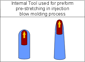 |
A tool behaves as external if it catches a preform / parison when moving from outside of the preform / parison to inside. In extrusion blow molding process, external tools can be used as a mold. In stretch injection blow molding process, an external tool is usually used as a mold tool.
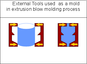 |
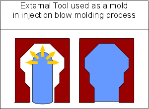 |
Description of tool movement is simplified in B-SIM from 2.2 version. Now, the initial tool position is not changed after tool load. To describe tool movement, specify shift vector and movements along this vector.
Shift vector definition
- X axis - tool moves in positive direction of X axis
- Y axis - tool moves in positive direction of Y axis
- Z axis - tool moves in positive direction of Z axis
- General - tool moves in direction of a vector specified by its components
Typical setting for various types of blow molding:
- Injection blow molding, stretch injection blow molding
Tools usually move in direction of Z axis
- Extrusion blow molding with or without parison pre-stretching
Tools usually move in direction of X or Y axis
- More advanced / sophisticated blow molding methods
Tools usually move in various direction (X, Y, Z axis) including general directions (these must be specified by shift vector components)
Starting from version 2.2, tool position in its *.tol
file (B-SIM Tool Document) is the initial tool position for every process
simulation.
This means that:
- If the tool position specified in process control data table is equal to zero, then the tool is located in the same position as in its *.tol file.
- If the tool position is equal to P, then the tool is shifted by P (mm or inches) in the direction given by shift vector
The following figures show how tools positions are specified in case of simple extrusion blow molding. There are two tools used, both moving in direction of Y axis and behaving as external.
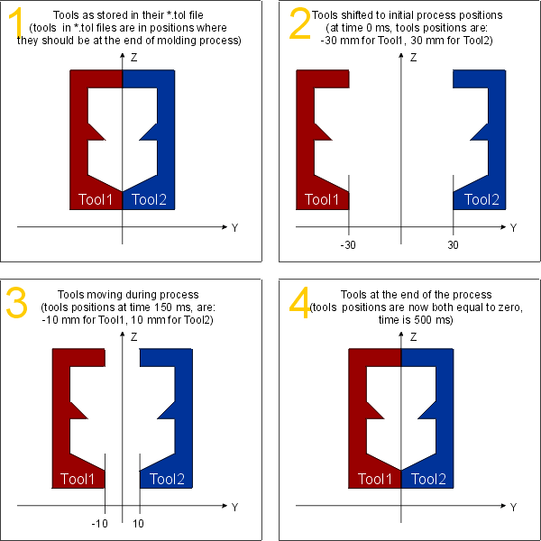 |
Here are the values & settings entered in the process control data table:
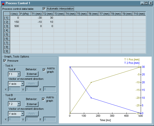
How to simulate different types of blow molding using B-SIM:
The following section describes how to simulate different processes using B-SIM. Please keep in mind that the tool movements & properties must be set up correctly in order to get right results. Please read the following section (and also the previous one) carefully before contacting us for support when having troubles with the process control description.
- Stretch - Injection blow molding (blow molding from injection molded preform)
-
In this case, preform is usually oriented along Z axis. This means that a stretching rod (if used) will move in direction of Z axis. The mold used must be set to behave as external. The stretching rod must be set to behave as internal. For more information about setting tool behavior see Process control creation and Tool behavior.
-
Extrusion blow molding with or without parison pre-stretching (blow molding from extruded parison)
In this case, preform is usually oriented along Z axis. Tools (parts of mold) can move in direction of X or Y axis, or even in a general direction. All tools used as a part of mold must be set to behave as external. Pre-stretching tools (if used) act on inner side of parison, so they must be set to behave as internal. They usually move in direction of X or Y axis. For more information about setting tool behavior see Process control creation and Tool behavior.
To learn more about setting process control, please see B-SIM Tutorial.
